
Home Made Vex Programming Cable
The Vex robotics kit is a great way to get started with robotics. The starter kit comes with many parts to construct a robot. It also comes with a radio transmitter and a reciver to remotely control the robot. The brains of the robot reside in a microcontroller module to which you can connect motors, servos, switches and sensors. The microcontroller can be programmed to read in sensor, switch and transmitter inputs and control the motors and servos. However, the starter kit does not come with any means to program the microcontroller. If you know how to program in C, all the software is available online for free. To write the software you can use MPLAB IDE available from Microchip and the student version of the C18 compiler (ver 2.4 required). Vexlabs also provides Vex starter code for free from their downloads page, along with the IFI loader to transfer your compiled code to the microcontroller. With all the software available, the only thing that is missing is a programming cable to trasfer the code from your computer to the microcontroller. As a result, I have decided to try to make a home made programming cable. Below is a picture of what I have created.
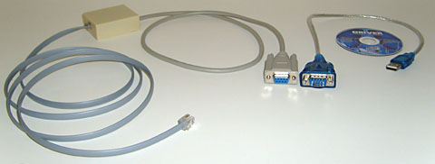
The programming cable consists of the following:
- RJ14 6-pin cable (5ft long)
- Home made programming module
- Serial cable permanently attached to programming module (2.5ft long)
- USB-to-Serial cable (1ft long)
- USB-to-Serial cable CD with drivers
One end of the RJ14 cable connects to the Vex microcontroller module and the other connects to the home made programming module. The RJ14 cable can detach from the programming module and a longer cable can be used if needed. On the other side of the programming module there is a permanently attached serial cable with a female connector. The female connector can attached directly to a serial port on a computer (if there is one). I also have a 1ft long USB-to-Serial cable so I can attach the programming module to a computer without a serial port. The drivers for the USB-to-Serial converter cable come on a mini CD and they work without a problem on my Windows XP computer.
I created the cable using information located on the ChiefDelphi forums and by doing some tinkering and verification. Using the information I found online I built a test circuit to see if the information was valid. It took quite a bit of experimentation but it looks like I finally figured it out (without destroying my microcontroller either!). The tricky part was confirming what each pin did. Since I don't own an oscilliscope or a logic analyzer, doing so proved a bit more difficult than it should have been. To overcome that I create a simple and cheap logic analyzer using an Atmel microcontroller that communicated with my computer through the serial port. Using that information, I was able to confirm what each pin was used for.
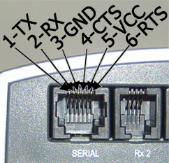
The image on the left shows the serial connector on the Vex microcontroller module. I don't know if there is any standard convention for numbering pins (left to right or right to left) but I chose to label them in increasing order, starting from the left and going to the right, as viewed looking into the connector. All the pins have a purpose:
Pin1=TXPin2=RX
Pin3=Ground
Pin4=CTS
Pin5=VCC at 5V
Pin6=RTS
Pins 4 and 6 (RTS and CTS) are used to do some handshaking in order to put the microcontroller into programming mode. Once the microcontroller is in programming mode, Pins 1 and 2 (TX and RX) are used to transfer a compiled program from a computer to the microcontroller. Pins 5 and 3 (VCC and Gnd) are used to power the electronics in the home made programming module. The Vex microcontroller module is connected to the programming module using the 6-pin cable show in the first image.
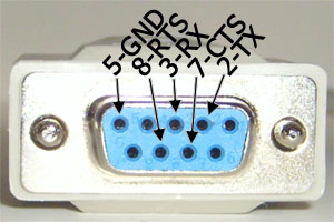
On the other end of the home made programming module is a serial cable with a 9-pin female connector. To the left is a picture of the connector with the pins labeled. Only 5 of the 9 pins are used:
Pin2=TXPin3=RX
Pin5=Ground
Pin7=CTS
Pin8=RTS
Pins 7 and 8 (CTS and RTS) are used in the handshaking to put the Vex microcontroller into programming mode. Then, pins 2 and 3 (TX and RX) are used to trasfer code from the computer to the Vex microcontroller.
The home made programming module contains a RS232 level shifter and a microcontroller. The level shifter is needed to convert the computer's serial port voltage levels to the voltage levels required by the Vex microcontroller. If a level shifter is not used, data won't be transfered and the higher voltage coming from the computer's serial port might also damage the Vex microcontroller. I also have an Atmel microcontroller in the programming module so that I can put the Vex microcontroller into programming mode. When using a USB-to-Serial converter cable, it somehow changes the signal coming from the computer and so the Vex microcontroller doesn't go into programming mode. The microcontroller intercepts the corrupted signal and produces the correct signal to put the Vex microcontroller into programming mode. I have tried using several different USB-to-Serial converters and the only reliable way of putting the Vex microcontroller module into programming mode was to add a microcontroller into the programming module.
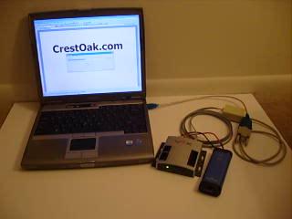
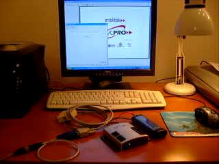
The resulting cable works well as you can observe in the short video on the left. The resolution of the video isn't that great, but you can see that I connected the Vex microcontroller module to my computer using my home made cable and I have the IFI loader with the correct port already selected. In the IFI loader, I also have already selected to upload the default code available from the vexlabs website. When I click on download, you can see that the programming light on the Vex microcontroller module goes on and the progress bar shows the downlad status. When the program finishes downloading, the light goes off and we are ready to go.
Note, that I have also tested the cable with an evaluation verson of EasyC Pro. As you can see in the video, I was able to download the code without any difficulties.
Like anything that is home made, there is no guarantee its use is risk free. So if you choose to use one of these, its at your own risk. However, I have made a couple of these cables and I've tested everyone of them and I haven't had a problem with them yet (probably did over 100 downloads already). They work reliably and I'm very satisfied with it. If you would like one of these cables, please get in touch with me at (picture of email address to avoid spam). Given the cost of all the components, I should be able to get you the programming cable along with the USB-to-Serial cable for around $35. In my opinion, it's a part that is missing from the Vex robotics kit. Once you have it, you can do so much more with the kit.